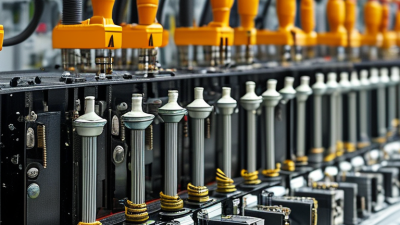
Harness manufacturing turns a wiring diagram into a dependable electrical assembly. It combines selected wires, terminals, connectors, seals, and protective coverings into a harness built for a specific machine or vehicle. The work may look simple from a distance. Up close, every detail matters: a terminal must sit correctly in its housing, and a branch must reach its connection without strain.
The process usually begins with engineering documents and a bill of materials. Technicians cut wires to length, strip insulation, attach terminals, and arrange each circuit on a board or fixture. They then add connectors, labels, sleeves, clips, or conduit as the design requires. A misplaced wire can disrupt an entire assembly. Small errors matter.
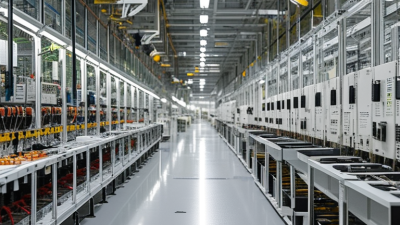
Quality checks are part of the work, not an afterthought. Depending on the design, manufacturers may inspect crimps, verify continuity, test for short circuits, and confirm connector locations. Production methods vary with order volume, application, and required performance. A high-volume automotive line may use specialized equipment, while a low-volume industrial build may need more manual handling. Neither approach removes the need for clear documentation and trained operators.
A specific expert quotation cannot be responsibly attributed without a verifiable source. Rather than invent one, this introduction uses a practical engineering principle: “A harness is only as reliable as its weakest connection.” The sections ahead explain the materials, production stages, testing methods, and common challenges behind harness manufacturing. There is no single recipe; even a proven process deserves review when designs or conditions change.
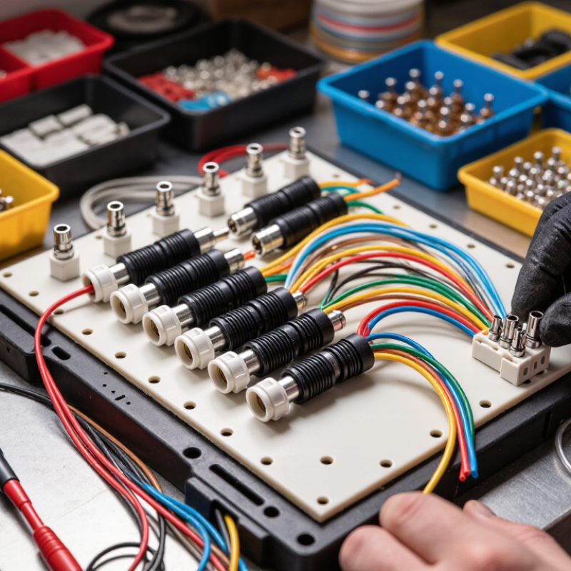
Harness manufacturing is the process of turning individual wires, terminals, connectors, and protective coverings into an organized electrical assembly. Each wire follows a planned route and connects specific points, helping equipment receive power or signals. The finished harness may include clips, labels, sleeves, or seals to suit its environment. Small details matter.
Harnesses are used in cars, household appliances, factory machinery, agricultural equipment, and many electronic devices. A vehicle harness, for example, can run behind a dashboard, where it must fit around controls and resist vibration. In a washing machine, wiring may need protection from moisture and repeated movement. Requirements vary by application, so one design rarely fits every product.
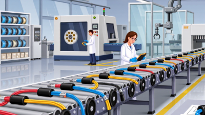
Production usually begins with drawings and a bill of materials. Workers or automated equipment cut wires to specified lengths, strip insulation, attach terminals, and insert them into connectors. The assembly is then arranged on a board or fixture, bundled, and checked for correct connections. Electrical tests can detect open circuits or unwanted connections. Visual inspection matters, too. A neat bundle can still contain a poorly seated terminal, and that flaw may be difficult to spot without a deliberate check.
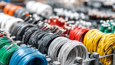
A cable harness is an organized group of wires that carries power or signals between parts of a machine. Its conductors form the electrical paths, while insulation keeps adjacent wires from touching. Wire size and insulation type depend on current, temperature, movement, and the surrounding environment. These choices are not cosmetic.
Terminals and connectors join the harness to components or other wiring. A crimped terminal grips the stripped conductor; a connector housing helps hold terminals in position and guides mating parts together. Some harnesses also include seals to limit moisture entry. A neat-looking crimp is not proof of a sound connection, so makers check dimensions and pull strength against the design requirements.
Protective sleeves, braided coverings, clips, and ties help route wires and reduce abrasion. Labels or color coding can make assembly and later service easier, though labels may fade or become hidden after installation. During manufacturing, wires are cut, stripped, terminated, bundled, and checked against a layout. Continuity and pin-position tests can catch wiring errors before shipment. A drawing can still miss a tight bend or awkward service access. Fit checks in the intended space often reveal those details. Small details matter.
| Harness Part | Typical Materials or Form | Main Function | Manufacturing and Design Considerations |
|---|---|---|---|
| Conductors and insulated wires | Copper conductors with polymer insulation; wire size and insulation type vary by application. | Carry electrical power or signals between components. | Wire gauge, current demand, voltage, temperature, flexibility, and routing length must suit the application. Wires are cut to specified lengths and identified for assembly. |
| Terminals and contacts | Conductive metal contacts, commonly made from copper alloys and often plated for corrosion resistance. | Provide an electrical connection between a wire and a connector, stud, or other electrical point. | Stripping length, conductor position, crimp height, and crimp force are controlled to create a secure electrical and mechanical connection. Crimp quality is checked during production. |
| Connector housings | Molded insulating housings, commonly made from engineering plastics. | Hold contacts in position and provide a mating interface for electrical connections. | Housing shape, contact layout, keying, retention features, and mating requirements must match the intended connection. Connectors may be assembled by inserting contacts into designated cavities. |
| Seals and grommets | Elastomeric seals or grommets fitted around wires or connector interfaces. | Help limit the entry of moisture, dust, or other contaminants where environmental protection is required. | Seal size and placement must match the wire diameter and connector design. Incorrect positioning or damage can reduce sealing effectiveness. |
| Splices and junctions | Crimped, welded, or otherwise joined conductors, typically covered with insulation or protective tubing. | Connect two or more wires to distribute power or signals within the harness. | Splice location, joint method, insulation coverage, and branch lengths are defined by the harness design. Joints should be protected against mechanical stress and exposure appropriate to the application. |
| Protective sleeving and conduit | Corrugated plastic conduit, braided sleeving, tape, or other specified covering. | Protect wire bundles from abrasion, heat, vibration, or contact with surrounding parts. | Protection is selected according to the installation environment. Openings, overlaps, and transitions should be secured without obstructing connector access or required movement. |
| Tape and bundle wrapping | Harness tape selected for the required temperature, abrasion resistance, and flexibility. | Bind wires together and help maintain the planned bundle shape. | Wrapping pattern and coverage are specified to keep branches organized while allowing the harness to flex where needed. Excessive tightness can stress wires or branches. |
| Clips, clamps, and fasteners | Molded clips, metal clamps, ties, or other mounting hardware. | Secure the harness to a structure and help maintain its routing. | Attachment locations and spacing are designed to limit movement, rubbing, and strain on connectors. The selected fastener must fit the mounting point and service environment. |
| Labels and identification markers | Printed labels, sleeves, tags, or other durable identification methods. | Identify wires, branches, connectors, or assembly references during installation and service. | Marking content and location are defined by the documentation. Labels should remain legible and attached under the expected operating conditions. |
| Assembly board and test records | Harness-specific fixtures, templates, and inspection or test documentation. | Support accurate routing during assembly and record checks on the finished harness. | Boards or fixtures help position branches and connectors to the specified layout. Typical checks include visual inspection, continuity, and verification of circuit connections against the approved design. |
Harness manufacturing begins long before wires reach a cutting machine. Engineers convert electrical requirements into a controlled design package. That package usually includes circuit lists, connector tables, wire specifications, pin maps, and a board layout. IPC/WHMA-A-620 remains a key industry reference for cable and harness workmanship criteria. It covers crimping, soldering, insulation, routing, and inspection practices.
Details matter. A single connector cavity can change the entire assembly sequence. Designers mark wire colors, cut lengths, strip dimensions, branch points, and protective sleeves. They also record revision levels and approved substitutions. According to the 2023 global wire harness market analysis by Grand View Research, automotive applications represented a major demand segment, driven by rising electrical content in vehicles. More circuits mean more documentation pressure. Small errors multiply quickly.
Digital tools help teams compare the schematic with the physical harness board. A technician can follow numbered routes, verify cavity positions, and record pull-test results. The documentation should show what happens, not what engineers hoped would happen. That distinction is important. IPC/WHMA-A-620 recommends objective acceptance criteria, but interpretation still depends on training and inspection discipline. Sometimes a drawing looks complete. It is not. Missing bend limits, unclear branch dimensions, or vague test instructions can create rework. Experienced teams review these weak points before production, although no review catches everything.
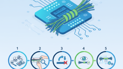
Harness manufacturing turns a wiring diagram into a tested, organized electrical assembly. The work starts with wire selection, then automated cutting and stripping. Machines cut each conductor to a specified length and remove a small section of insulation without nicking the copper. Not glamorous. Yet a damaged strand can weaken the finished connection.
Operators or automatic applicators attach terminals by crimping, which compresses metal around the conductor and insulation. Crimp height and pull strength are checked against the work specification; visual inspection alone can miss a poor joint. IPC/WHMA-A-620 provides widely used acceptance criteria for cable and wire-harness assemblies. A Fortune Business Insights report valued the automotive wiring harness market at about USD 47.4 billion in 2023, reflecting the scale of demand for consistent production. Terminated wires are then routed through fixtures, branches are secured with tape or ties, and connectors are installed in their assigned positions.
The harness is tested for continuity and shorts before release. Some assemblies also receive resistance or insulation checks, depending on their design. Test results matter. A wire can look perfectly routed and still fail electrically. Fixtures help maintain repeatable branch lengths, though real production can be less tidy than a diagram suggests. Small layout changes may require careful rework, not just a faster machine.
A finished harness is checked before it is packed or installed. Technicians compare its wires, terminals, connectors, and labels with the approved drawing. They look for loose crimps, damaged insulation, bent pins, and missing seals. Small defects matter. A terminal that sits slightly crooked may fail after repeated vibration.
Electrical testing checks whether each circuit connects to the correct point. A continuity tester can reveal open or crossed wires, while insulation resistance tests help identify unwanted paths between conductors. For some assemblies, technicians also verify resistance, shielding, or signal performance. The test plan depends on the harness design and its operating conditions. Results are recorded against the unit or production batch, making problems easier to trace. Testing has limits, though. A bench check cannot reproduce every temperature change, movement, or installation mistake. That is worth remembering.
After inspection, protective caps or covers keep connector faces clean. The harness is coiled without sharp bends, secured gently, and placed in packaging that prevents crushing and moisture exposure. Labels should remain readable and match the build records. Before use, installers can inspect the package, confirm the part identification, and check that connectors are undamaged. A careful handoff helps, but it is not a substitute for verifying fit and routing in the actual equipment.